Free cad designs files 3d models
Table of Contents
Table of Contents
If you’re interested in mechanical design and engineering, you may have come across the term “bevel gear”. Bevel gears are a type of gear with angled teeth that are used to transfer power and motion between two intersecting shafts. Drawing a bevel gear can seem daunting, but it’s an essential skill for anyone working in mechanical design. In this article, we’ll explore how to draw a bevel gear in detail.
When it comes to drawing a bevel gear, there are several challenges that can arise. It can be difficult to accurately represent the complex shape of the gear teeth, and understanding the precise angles and dimensions required can be tricky. Additionally, different types of bevel gears may require different drawing techniques, adding to the complexity of the task.
The first step in drawing a bevel gear is to research the specific type of gear you want to draw. This may involve consulting technical drawings or specifications to gain a better understanding of the gear’s dimensions and angles. From there, you’ll need to choose the appropriate drawing tools and techniques, such as using a CAD program or drawing by hand with precise measurements.
In summary, drawing a bevel gear requires careful research, attention to detail, and the right tools and techniques. By following the steps outlined in this article, you can learn how to draw a bevel gear and improve your mechanical design skills.
Step-by-Step Guide to Drawing a Bevel Gear
As someone who’s worked in mechanical design for years, I’ve had my fair share of experience drawing bevel gears. In this section, I’ll share my personal process for drawing a bevel gear, step by step.
First, I start by doing thorough research on the specific type of bevel gear I want to draw. This may involve consulting technical specifications or drawings to gain a better understanding of the gear’s dimensions and angles.
 Next, I begin sketching out the basic shape of the gear. I start with a rough outline of the gear’s overall shape, and then begin adding in the individual teeth. It’s important to pay close attention to the angles and spacing of the teeth, as these will determine how the gear will function.
 ### Tips for Drawing Bevel Gears
When drawing bevel gears, there are several important tips and considerations to keep in mind. First, accuracy is key – even small measurement errors can lead to non-functioning gears. Second, it’s important to choose the right tools and techniques for the job. Many designers prefer to use CAD software for precise measurements and ease of editing, while others prefer to draw by hand for more flexibility and control.
Common Mistakes to Avoid when Drawing Bevel Gears
One of the most common mistakes when drawing bevel gears is not paying close enough attention to the dimensions and angles of the teeth. It’s essential to do thorough research and double-check all measurements before beginning to draw.
Conclusion of How to Draw a Bevel Gear
Learning how to draw a bevel gear is an important skill for anyone working in mechanical design. By researching the specific type of gear, paying attention to details such as tooth angles and dimensions, and using the right drawing tools and techniques, you can create accurate and functional bevel gears that will help power a wide range of mechanical devices.
Question and Answer
Q1: What materials do I need to draw a bevel gear?
A: The materials you need to draw a bevel gear will depend on your preferred drawing method. If you’re drawing by hand, you’ll need high-quality pencils, erasers, rulers, and possibly a compass or protractor. If you’re using CAD software, you’ll need access to a computer and the appropriate software program.
Q2: What are the different types of bevel gears?
A: There are several types of bevel gears, including straight bevel gears, spiral bevel gears, and hypoid bevel gears. Each type of gear has slightly different angles and dimensions, so it’s important to research and choose the appropriate type for your specific application.
Q3: Can I draw a bevel gear without using CAD software?
A: Yes, it’s possible to draw a bevel gear by hand using precise measurements and drawing tools. However, using CAD software can make the process easier and more precise, especially for complex gears with many teeth.
Q4: How do I know if my bevel gear is functional?
A: To determine if your bevel gear is functional, you may need to build a physical prototype or consult with a mechanical engineer or expert. However, if you’ve followed accurate measurements and tooth angles, your gear should function properly in theory.
Gallery
Bevel Gear - Inventor Part Design | 오토캐드, 기술 도면, 스케치

Photo Credit by: bing.com / bevel inventor autocad autodesk tecnico solidworks 기어 orthographic mecanico tistory 도면 mecanicos técnicas meccanica interessante geometria ingegneria ingranaggi linguaggio deckel
Figure 10 From Design And Analysis Of A Spiral Bevel Gear | Semantic

Photo Credit by: bing.com / bevel
Precision Bevel And Miter Gears Manufactured By SDP/SI

Photo Credit by: bing.com / bevel miter drawing gears precision tech sdp si iso class tooth
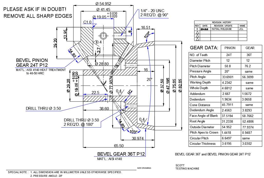
Bevel Gear 36T And Bevel Pinion Gear Section Detailed Drawings Are

Photo Credit by: bing.com / bevel autocad pinion dwg 36t given cadbull
Free CAD Designs, Files & 3D Models | The GrabCAD Community Library
Photo Credit by: bing.com /


